![]()
![]()
![]()
![]()
![]()
![]()
![]()
![]()
![]()
![]()
![]()
![]()
![]()
![]()
![]()
![]()
![]()
![]()
![]()
Boat: Rhumb Do Date: August 2020
My steering system appears to be bombproof with substantial joints and 1" diameter tubes throughout, so apart from applying grease to the two nipples on the tie rod ends, I have done very little to it - big mistake!!
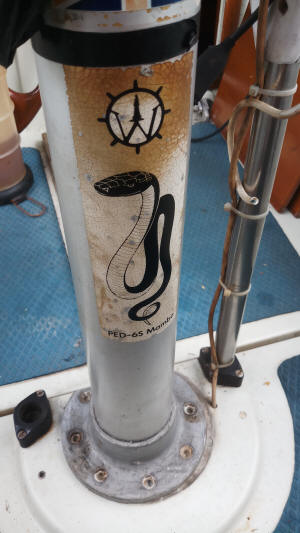
The boat is fitted with a Whitlock Mamba steering pedestal which is connected to the rudder quadrant via torque tubes which are converted to linear movement at the final transfer/reduction gearbox. The "ultimate" steering system according to Lewmar!
The pedestal is a PED-6S model from when Noah was a boy and there are neither drawings nor parts available anymore, which is problematic when you have a total steering failure as you come in to anchor in a small 'pond!'
We had just completed a 180NM trip from Labuan to Kudat around the northern tip of Borneo and were entering the pond when there was a graunching noise from the pedestal and all steering ability went out of the window.
My preliminary inspection revealed that the output shaft from the bevel gearbox immediately under the deck at the base of the pedestal, was not responding to any wheel movement.
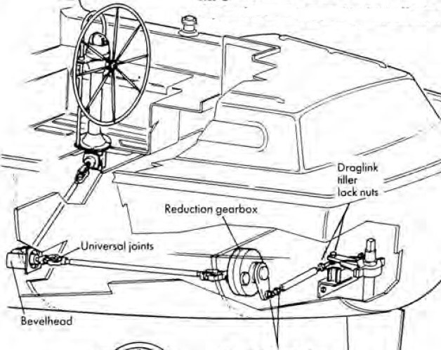
Universal joint connects the bevelhead gearbox output shaft to the torque tubes.
The above drawing shows a similar set up to mine. On mine the torque tube comes from the bevelhead gearbox at the base of the pedestal directly to the reduction/transfer gearbox, where the rotary movement is converted to linear movement and then via a long torque tube to the rudder head. On this tube are ball joints/tie rod ends/drag links at each end (depends where you are from as to the name!)
When I started to strip down the system, it was obvious that someone else had done a few repairs or modifications in the past, and advice from fellow Warrior owners did not fit with what I was actually seeing and experiencing.
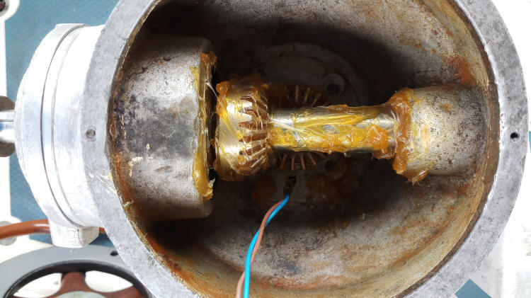
This is the bevelhead gearbox stripped down. The arrowed male splines are worn away as are the matching female splines on the pedestal downshaft. The two roller bearings and the two needle bearings are also worn. The two oil seals were leaking.
The pedestal bowl with the compass and top plate removed. The shaft you can see is the steering wheel input shaft. To the right is the bearing carrier housing, to the left is the shaft end bush.
The same view with most of the grease removed, the bearing carrier removed and both the steering input shaft and the pedestal downshaft withdrawn. Withdrawal of the pedestal downshaft (according to Whitlock) has to be done from the top - but that is impossible because the (modified) female splined fitting at the bottom of the shaft will not pass through the bearing! At the top of the shaft are two roller bearings, in the pic, the upper one has been removed, the lower one is still in place. The lower bearing carrier is secured to the bowl by the four visible studs and nuts, which means you would need a 40" long extension bar to undo them from the bottom of the pedestal, that's if there was room between the nuts and the side of the pedestal in which to fit a socket - which there is not! In my case, the lower bearing seemed to be OK, no play or roughness in rotation, so I decided to leave well alone and concentrate on the obvious faults.
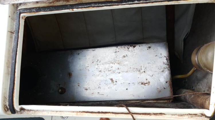
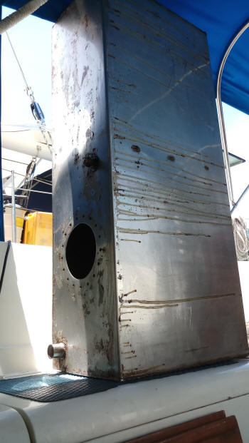
Removing the second gearbox inline, (the transfer or reduction gearbox) which changes rotary action into linear proved to be a major challenge. It is deep in the port cockpit locker at the after end of the fuel tank, beside the calorifier tank and under the bilge pump! After several days of trying to remove it from it's bracket, we decided the only way was to first remove the fuel tank to allow some access. I cut away the fibre glass that secured the top of the tank, pumped out 120 litres of fuel and then struggled to get the tank out of the locker - the aperture is just big enough!
The tank contained a lot of slimy jelly like substance (not diesel bug) but clear, like the dead jellyfish you might see washed up on the beach. I suppose that is another problem solved for a while - at least I will have a clean tank for a few years!
With the fuel tank removed, I was able to then undo the three bolts that secured the gearbox to it's steel bracket. The pic shows the box as it came out, the top vertical shaft connects to the arm which operates the torque tube leading to the rudder quadrant, The smaller splined shaft at the front is the input shaft from the bevelhead gearbox under the pedestal. Beneath that is a plastic oil drain/filler plug and the box is full of heavy duty gear oil. Turning the input shaft showed quite a bit of stiffness, so I stripped it down to it's component parts, as in photo below.
The lower bevel gearbox on the left and the transfer box on the right, re-assembled and ready to install. The splines on the input shaft of the bevel gearbox have been ground off and made into a hexagonal shape. The matching fitting on the pedestal downshaft has had a box spanner welded into the female splines to fit the hexagonal shape on the bevel gearbox input. All bearings have been renewed.
Re-assembly of the whole system was much easier than taking it apart! With no drawings, I was working in the dark when removing all the parts, whereas putting it back together was a walk in the park (almost!)
The pedestal bowl re-assembled.
1st bevelhead gearbox installed, along with the torque tube to the transfer gearbox.
The transfer gearbox installed on it's bracket. This photo is taken from where the fuel tank would be positioned, so you can see the confined space in which I had to work. It is impossible to work on the gearbox with the fuel tank in position.
The fuel tank back in the cockpit locker.
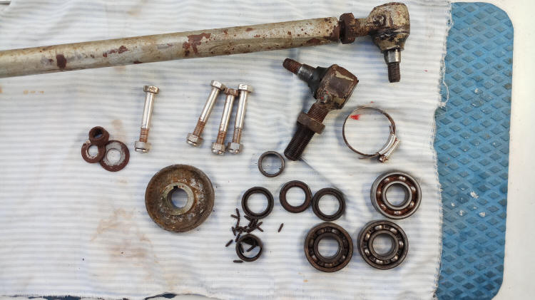
Just a few of the replaced parts.
During this overhaul of the steering, I had considered, priced and looked at the possibility of taking the whole lot out and replacing it with a hydraulic system. It would be possible but would entail doing away with the pedestal and mounting the steering wheel on the cockpit forward bulkhead, re-siting the engine instrument panel and making new hatches in the cockpit floor for access to the engine - which would be good, as it would give access to the shaft and currently inaccessible stern gland. But......it's not a job I want to take on at this stage!
The only remaining job to do on the steering now is to 'drop' the rudder and check the seals/bearings there - which is one of the main reasons I sailed up to Kudat on this occasion!
More to follow when I haul out.
Due to Covid 19 restrictions and bans on intercountry/district travel, my haul out is delayed for the foreseeable future. I see no point in hauling, antifouling and then sitting at anchor for months, unable to go anywhere, while the bottom fouls up again!
February 2022 After 19 months at anchor, we finally hauled out and I was able to drop the rudder for inspection!
Removal was much easier than I imagined it might be. The boat was positioned so that the keel rested on concrete blocks about 10" high and I needed to dig a hole under the rudder about a foot deep for the rudder stock to clear the rudder tube.
After placing wooden blocks under the rudder - it weighs around 60Kg, I removed the two bolts securing the 'shoe' which supports the bottom of the rudder. I had replaced these two bolts five years ago with ones of 304 stainless steel (all that was available at the time) and these showed signs of cavity corrosion on the threaded areas. They are 3/8ths bolts and I am replacing these with 10mm 316 stainless bolts.
From the aft cabin, I removed the torque bar tie rod end from the rudder arm (quadrant), loosened the clamp bolt and tapped off the arm - which really is just a short 1/2" thick steel bar. The rudder was then free to drop onto the wooden blocks placed below and gradually lowered out of the rudder tube.
I inspected the rudder stock and was relieved to see there was no corrosion or cracks visible, which had been a concern of mine as I have no idea when the rudder was last removed - certainly not during my ownership.
The top of the rudder tube holds a lipseal to keep sea water from entering, which is held in place by a circlip. I removed these for replacement. Inside the tube are two (one at the bottom, one at the top) plastic/nylon bushes about 2" each in length. Both seem to be in good condition.
The bottom spigot of the rudder fits in a composite bush held in place by the rudder shoe, this was showing signs of wear, so I had another one made.
Refitting was a reversal of the removal and I used a small hydraulic jack to push the rudder up into place before refitting the shoe.


.jpg)
.jpg)
.jpg)
.jpg)
.jpg)